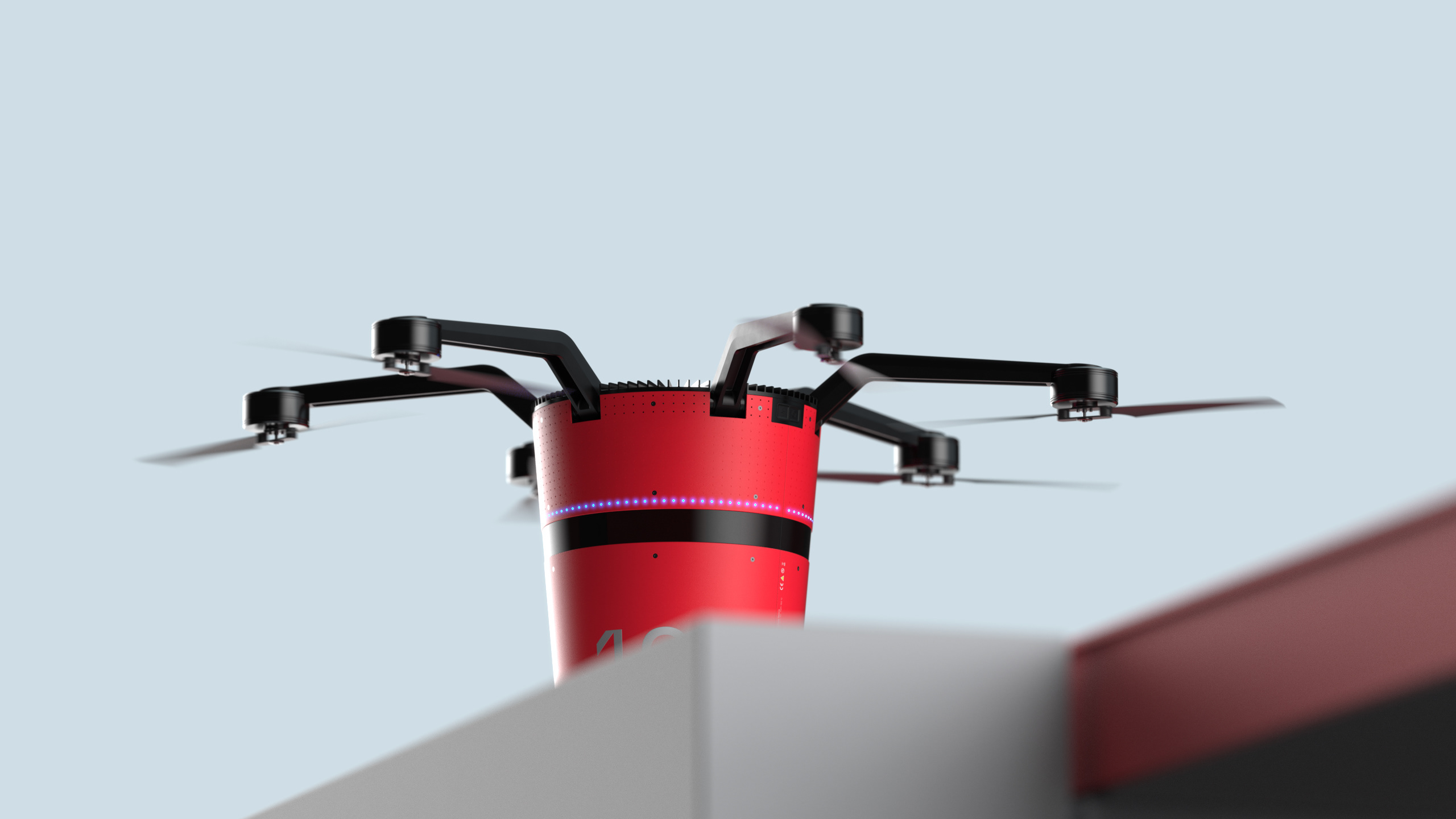
STRYDA is an autonomous inspection drone for sewer environments. Equipped with cross lasers and high-resolution cameras, the drone inspects the inside walls of sewers and manholes for cracks, deformations and leaks. With its eight rotors, it achieves a flight time of up to 40 minutes. The circumferential rim creates a cushion of air near the ground to extend the flight time and provides buoyancy in the water in the event of an accident. All the technology is installed in a waterproof and dustproof enclosure and does not require any moving parts.
Designed by Fiona Verhoeven and Simon Bruhns in cooperation with the Fraunhofer IFF Institute in Magdeburg, Germany.
/w Fiona Verhoeven
#semesterproject
#octacopter
#inspection
#amphibious
#fusion360
#keyshot3d

BRIEF
Surface view of a manhole
Opening of a manhole
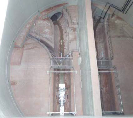
Top view into a manhole
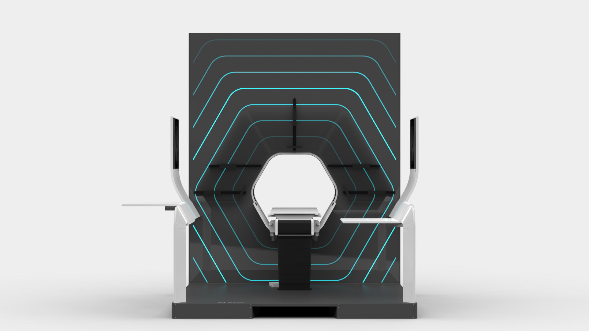
The aim of this project was to design an inspection drone for large sewers and manholes, such as the newly built Emscher sewer in the Ruhr area in Germany. Such sewers have a diameter of 1.6 m to 2.8 m. The manholes are up to 12 m in diameter and up to 40 m deep. Inside the structures, conditions are inhospitable to humans. For this reason, the inspection and cleaning of the systems should be as automatic as possible.
Until now, manually controlled wheeled and floating robots carried out the inspection and cleaning of the sewers, while the manholes were inspected by workers. A new inspection system should be able to inspect the manhole as well as the sewer. At first, a drone that both flew and floated seemed obvious. But after calculating the flight time through the canal, it turned out that a purely flying solution is also possible. This drone has to meet special requirements, as it has little space, especially in the canal, and no stable radio connection to the outside. We therefore decided on an autonomous drone control system.

CHALLENGES
The decision to go with a purely flying autonomous solution presented two design challenges.
Firstly, the drone must be equipped with sufficient sensors and software to navigate the manhole and sewer without radio communication or GPS. We equipped the drone with 10 lidar sensors and accelerators to redundantly calculate a 6D position. Furthermore, the entire flight route is planned in advance based on 3D data of the structures. The drone follows the planned route and validates the position with the sensor data.
Secondly, the battery capacity must be sufficient to reach and survey the sewers, which can be up to 1.2 km long. We calculated a flight speed of 1 m/s assuming a photo frequency of 4 pictures per second. This results in a maximum inspection time of up to 20 minutes for each manhole and sewer. A flight time of more than 20 minutes is easily achievable for larger multicopters, but the additional measuring instruments add weight, which reduces the flight time.
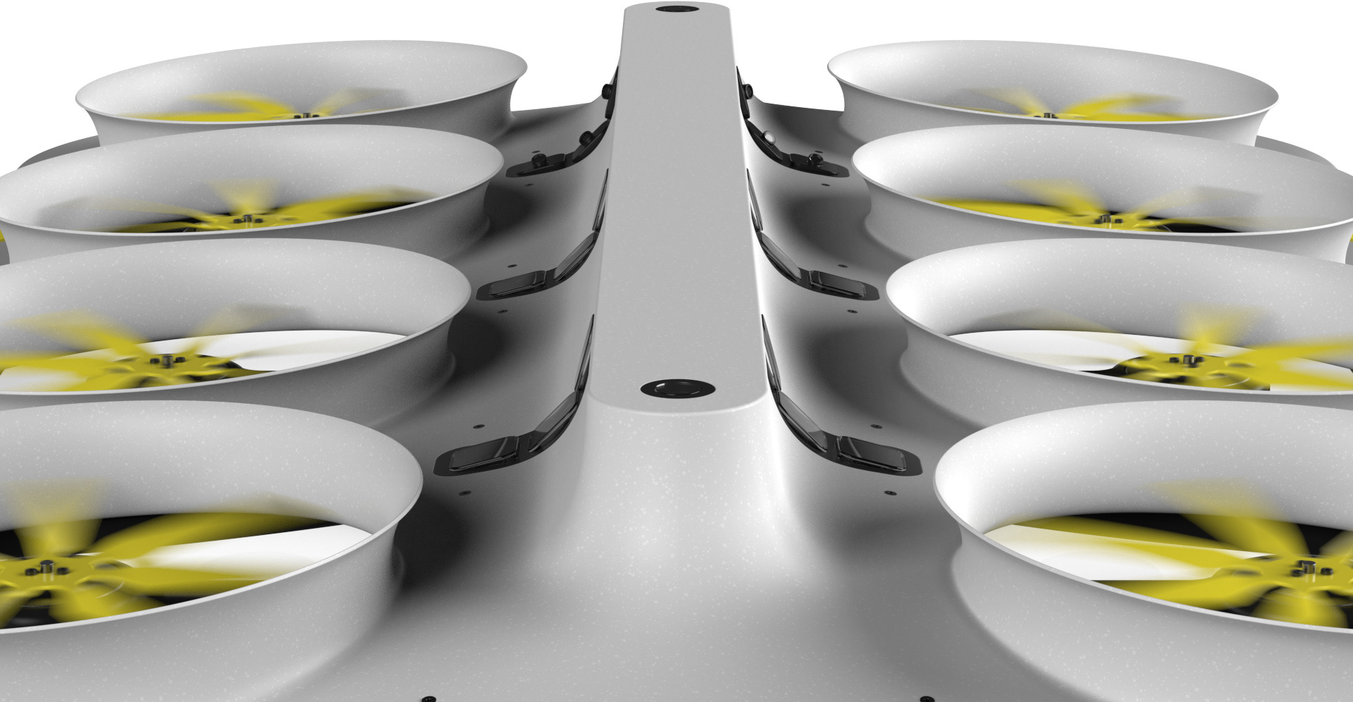
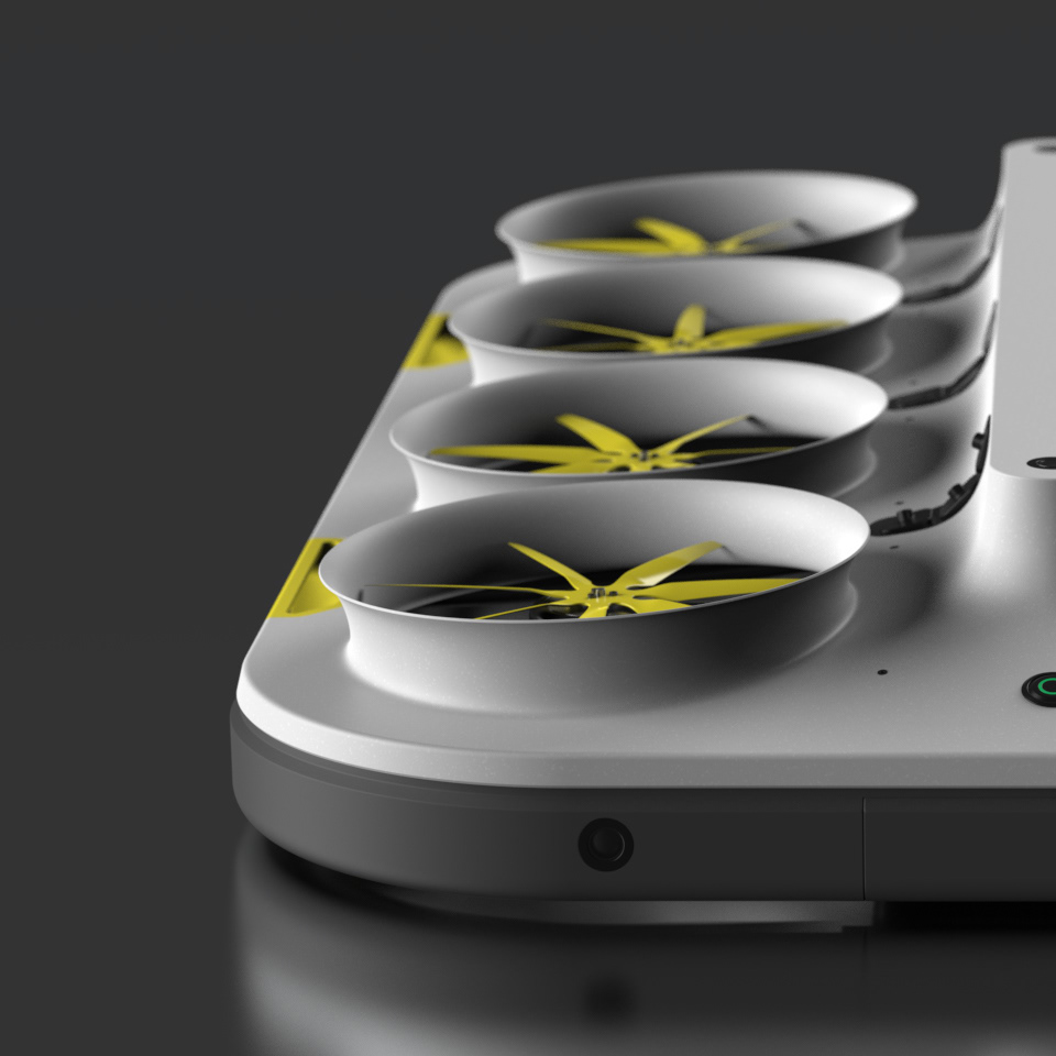
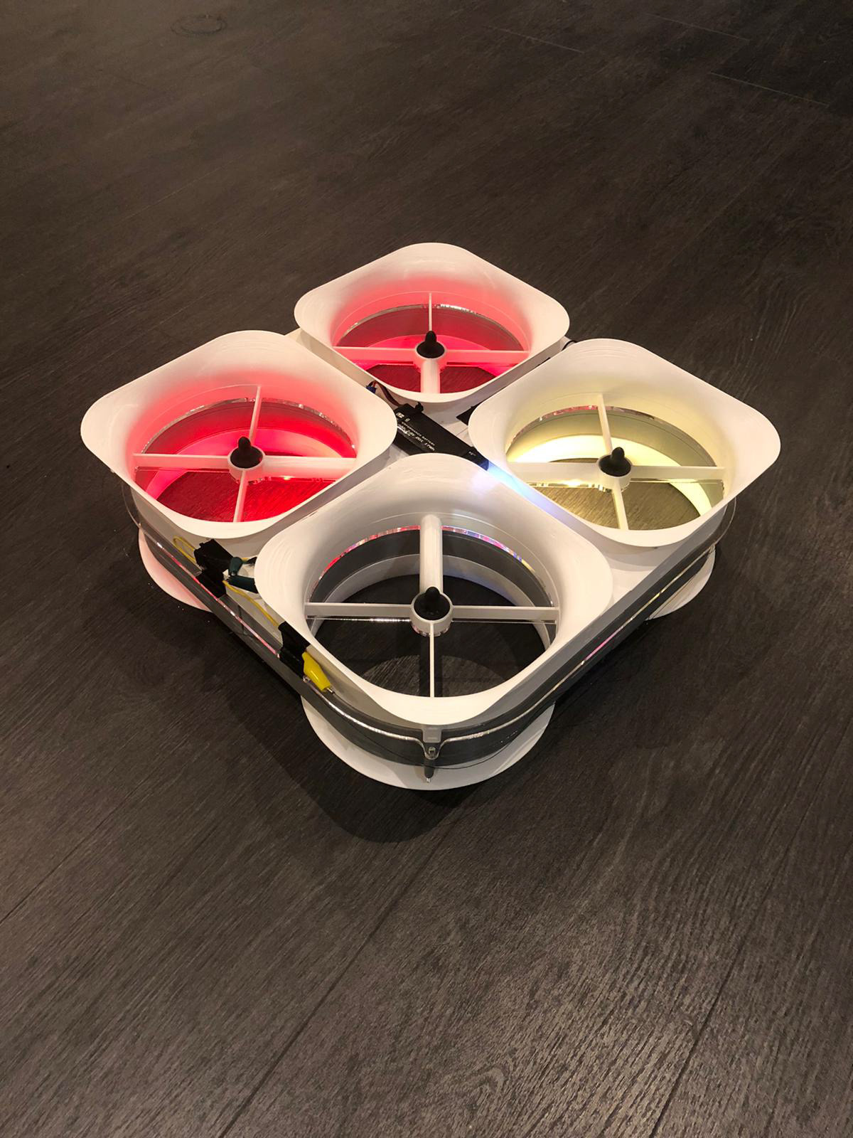
To compensate for this, we looked for ways to make the drone as efficient as possible. The lower the load on the motors, the higher the lift per energy consumed. Also, larger rotors are more efficient.We therefore decided to use eight 12" rotors, which resulted in an average motor load factor of 50%. The efficiency of the rotors can be further improved with ducts, as the air intake provides further lift through the Bernoulli effect on the duct surface. For this, the ducts must form a trumpet-shaped opening above the rotors. Since the drone flies in the sewer close to the ground, we use an air cushion under the drone in this phase, which increases the lift.
To test the latter effects, we developed a 3D-printed quadcopter. We fitted it with different ducts and skirts in various lengths and shapes to test their efficiency. The result was that both the ducts and the skirt already increased the efficiency. The shape of the ducts and skirts was less relevant than the overall length, which increased the efficiency significantly.

CONCEPT
We developed the drone based on the test results and calculations.
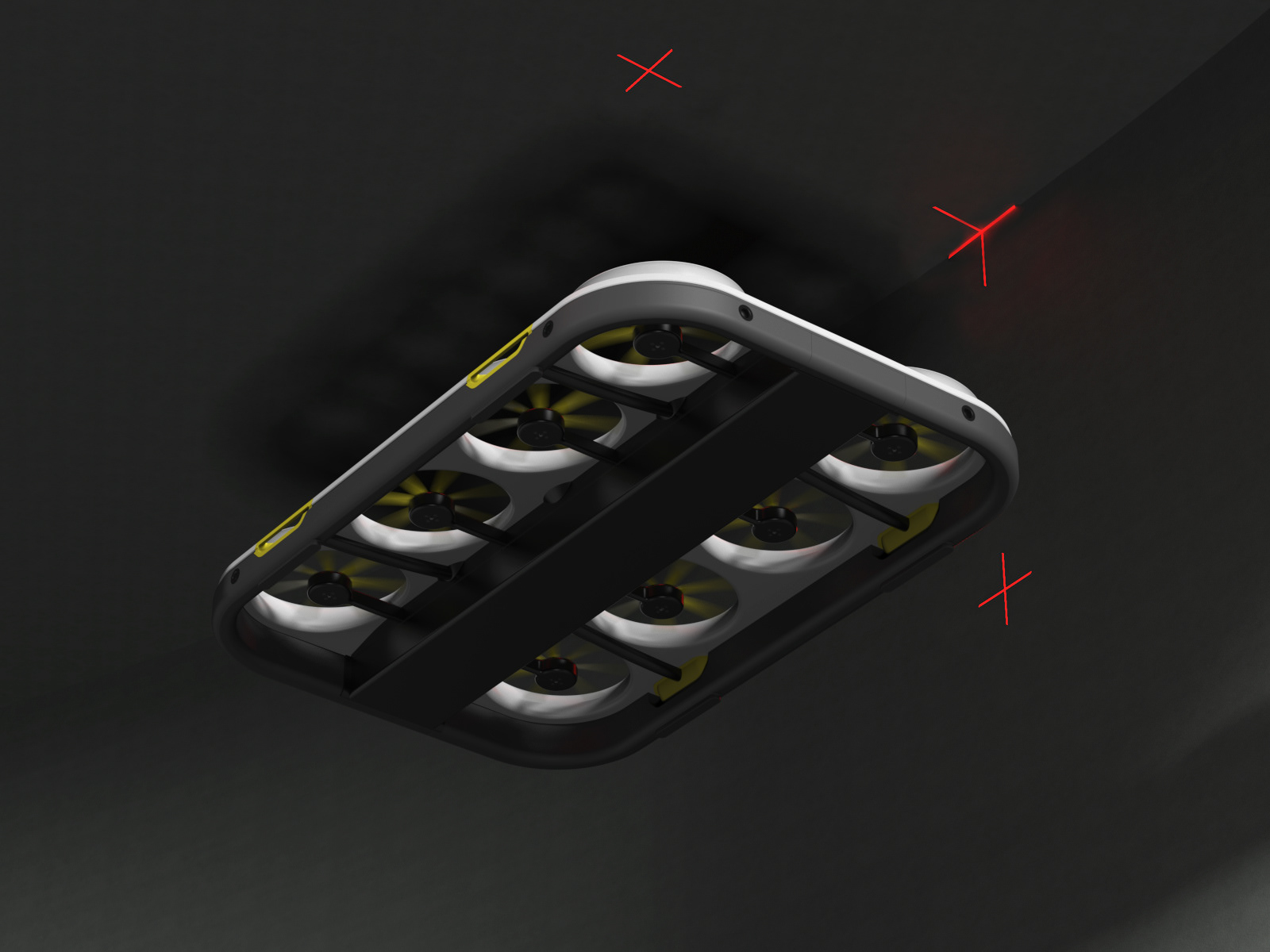
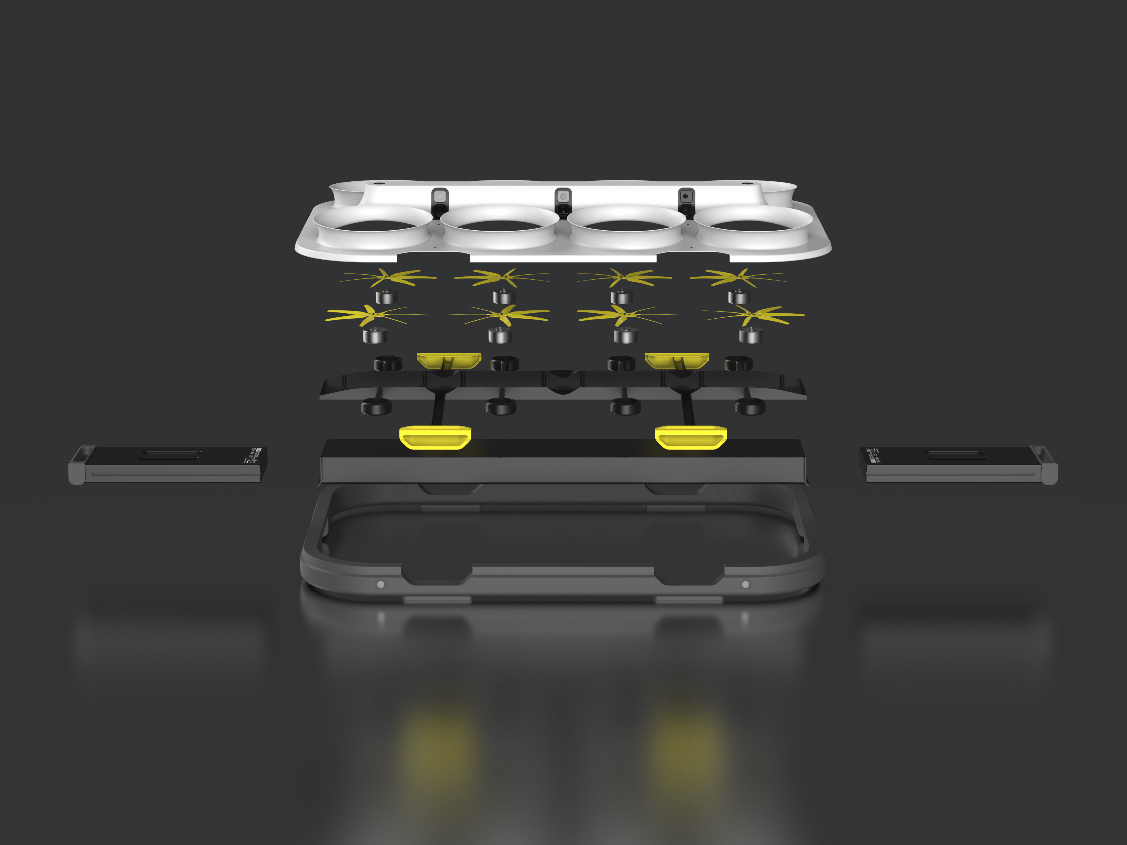
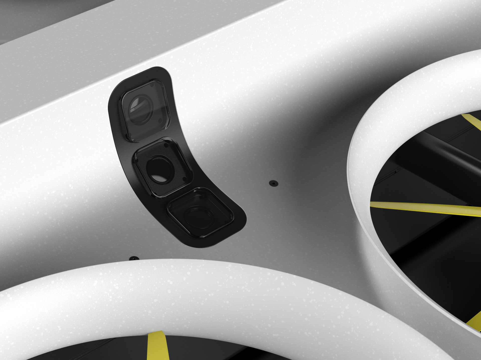
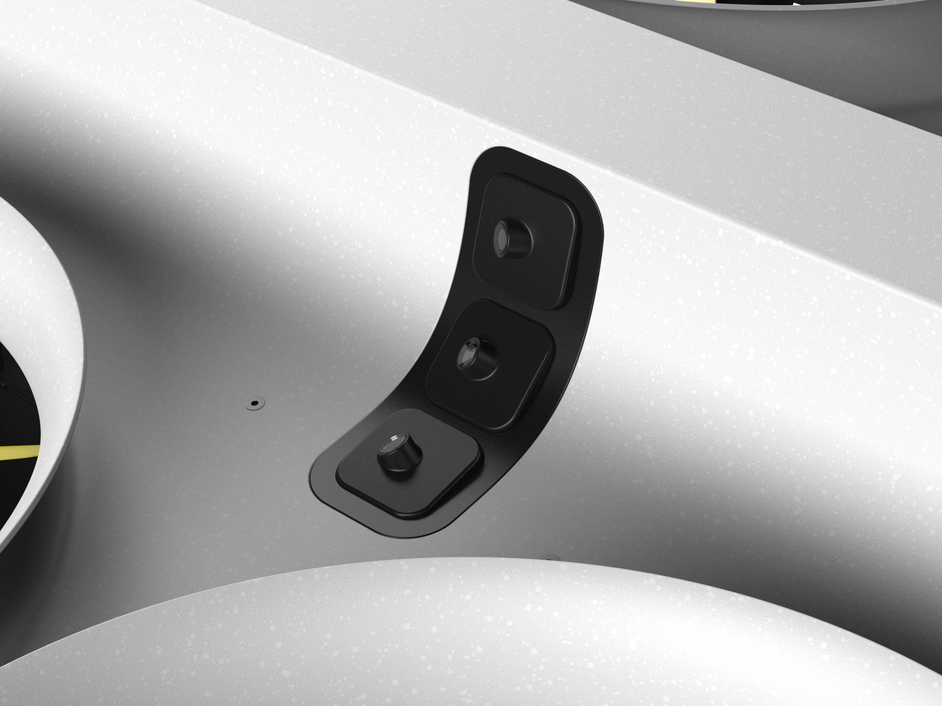
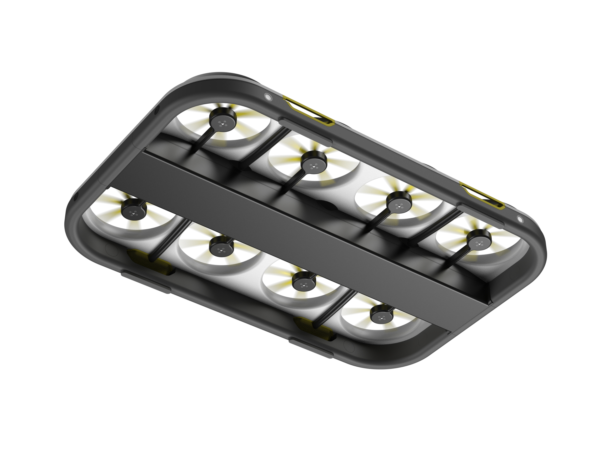
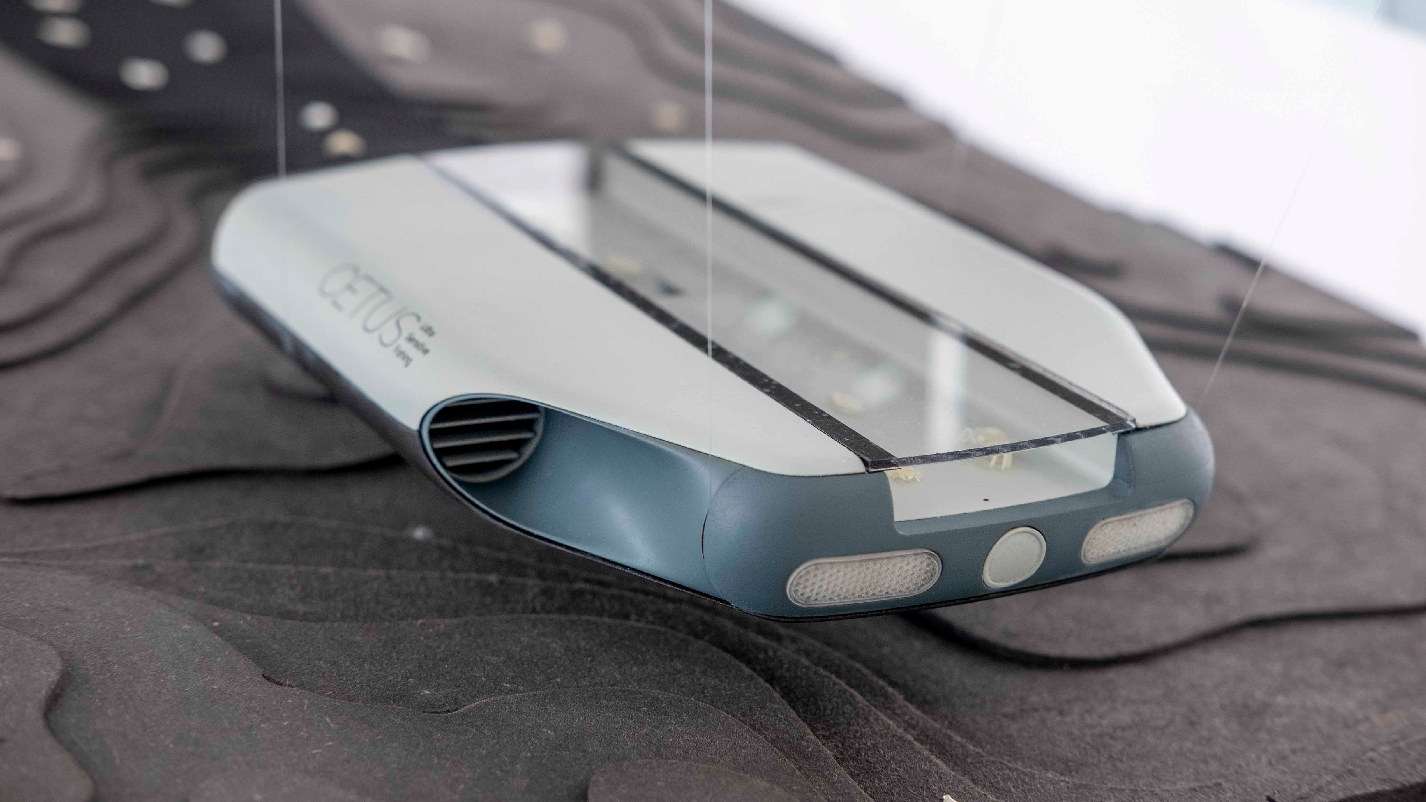
The 8 rotors in H-arrangements provided a width of 100 cm and a length of 150 cm with a weight of 20 kg. For inspection we used six fixed sets of camera, cross laser and LED flash. Alternately, one photo is taken with the flash and one with the cross laser. From the cross-laser photo, the geometry and deformations can be detected by trinangulation, and from the flash photo, cracks and dirt can be detected. For triangulation, the laser and camera must be as far away as possible, which is why the six cameras are located at the rear end, the lasers at the front end and the flashes in the middle of the drone. They are aligned to cover an arc of over 180° above the drone, which is sufficient for inspection. The measuring instruments are sealed waterproof on the outside and sit in a central compartment, which also contains the batteries. The batteries are also sealed watertight and can be unlocked and replaced by a push-to-open mechanism. The rotors and the outer frame are attached to the compartment. The outer frame represents both the skirt and the floating structure in the event of an emergency ditching. The upper shell forms the ducts, provides the angles for the measuring instruments and prevents the air cushion from escaping between the rotors. At each long end of the drone are two handles that can be used to lift the drone by two, four or a crane.
The 8 rotors in H-arrangements provided a width of 100 cm and a length of 150 cm with a weight of 20 kg. For inspection we used six fixed sets of camera, cross laser and LED flash. Alternately, one photo is taken with the flash and one with the cross laser. From the cross-laser photo, the geometry and deformations can be detected by trinangulation, and from the flash photo, cracks and dirt can be detected. For triangulation, the laser and camera must be as far away as possible, which is why the six cameras are located at the rear end, the lasers at the front end and the flashes in the middle of the drone. They are aligned to cover an arc of over 180° above the drone, which is sufficient for inspection. The measuring instruments are sealed waterproof on the outside and sit in a central compartment, which also contains the batteries. The batteries are also sealed watertight and can be unlocked and replaced by a push-to-open mechanism. The rotors and the outer frame are attached to the compartment. The outer frame represents both the skirt and the floating structure in the event of an emergency ditching. The upper shell forms the ducts, provides the angles for the measuring instruments and prevents the air cushion from escaping between the rotors. At each long end of the drone are two handles that can be used to lift the drone by two, four or a crane.

INSPECTION PROCESS
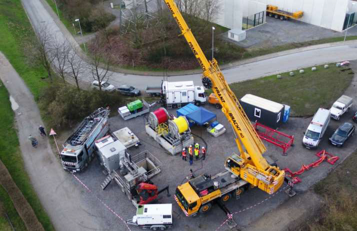
Unlike previous inspection systems, the drone only requires a car or van and two operators for the inspection. In the forefront of the inspection, the inspection flight is digitally planned and loaded into the drone. Thanks to the 3D data set, the inspection time can be planned in advance and any battery changes can be scheduled.
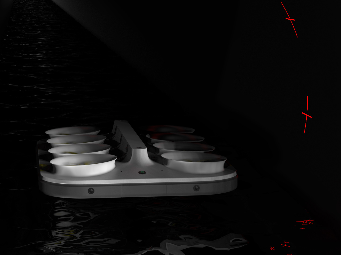
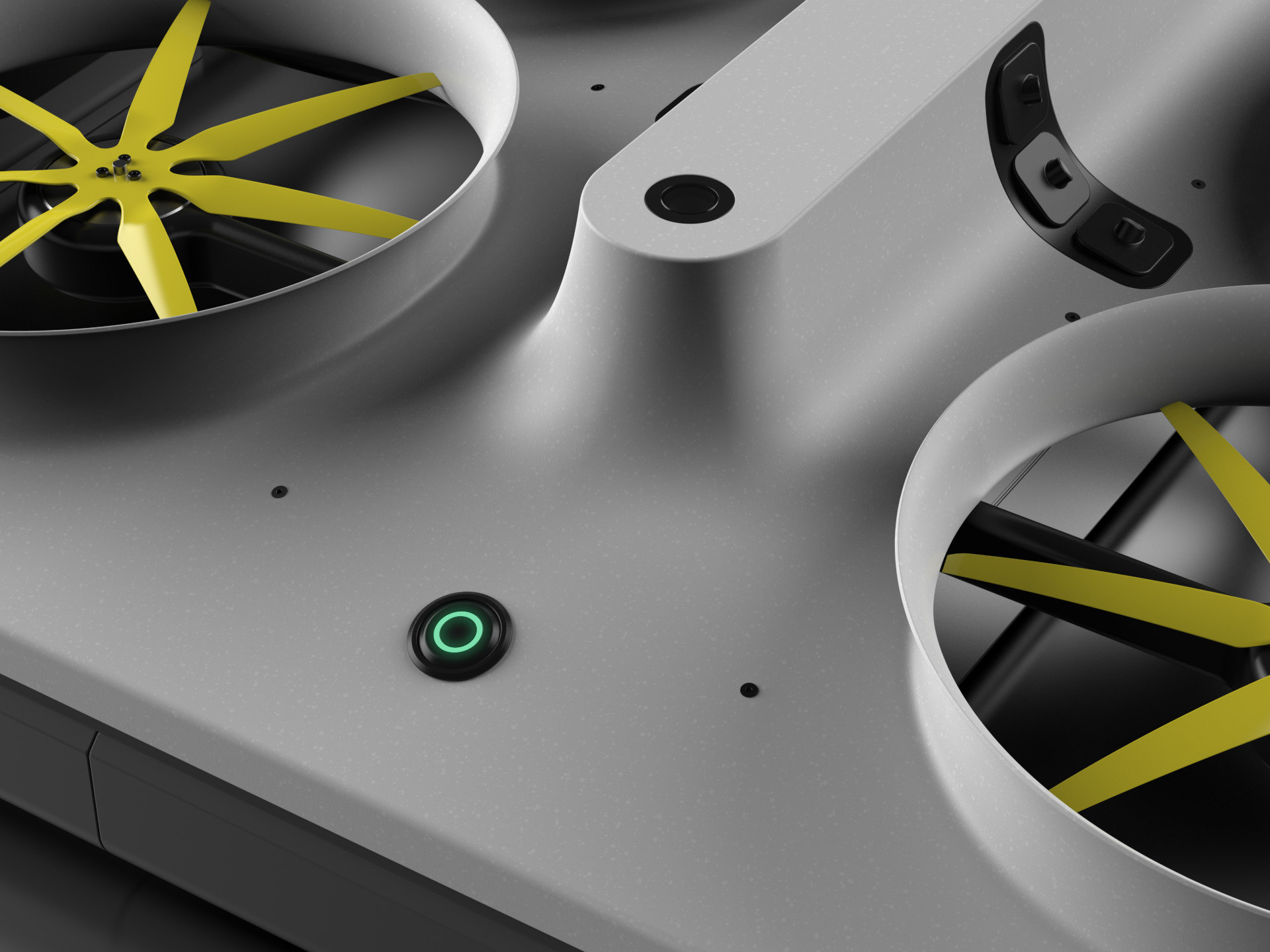
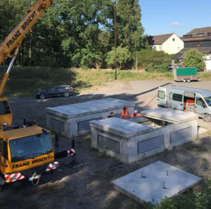
After the drone has been delivered, unloaded and placed next to the manhole opening, the battery is inserted and the drone is started by pressing the green button. The drone then flies into the manhole and begins the inspection. In a spiral movement, it flies across the ceiling and the wall of the manhole, taking alternating photos of the cross-laser projections on the wall and of the illuminated wall. The inspection of the sewer follows in the opposite direction to the flow direction, in which it again alternately inspects the geometry and surface of the surrounding sewer wall.
After a successful inspection, the drone flies back into the manhole and lands at the starting position. The collected data can then be loaded from the drone and analysed on site. In the event of an accident in the narrow sewer environment, the drone lands in the water and is flushed back into the manhole, where it is recovered.
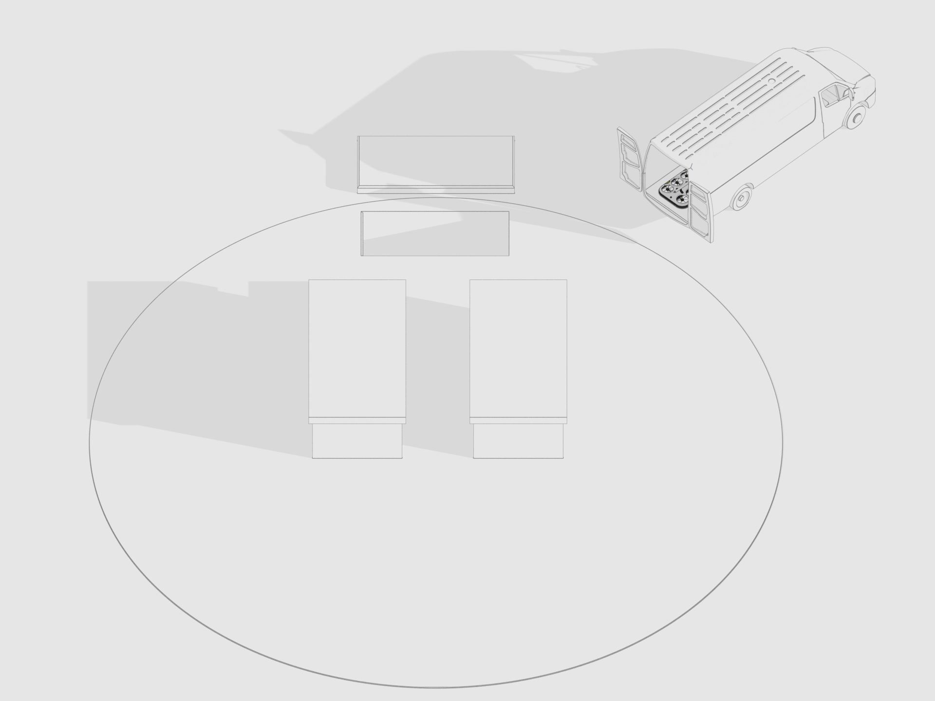
Arriving at the manhole.
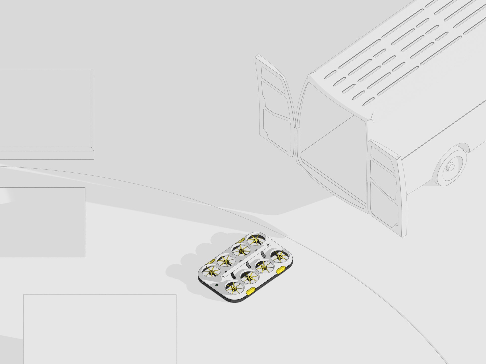
Unloading the drone from the car or van.
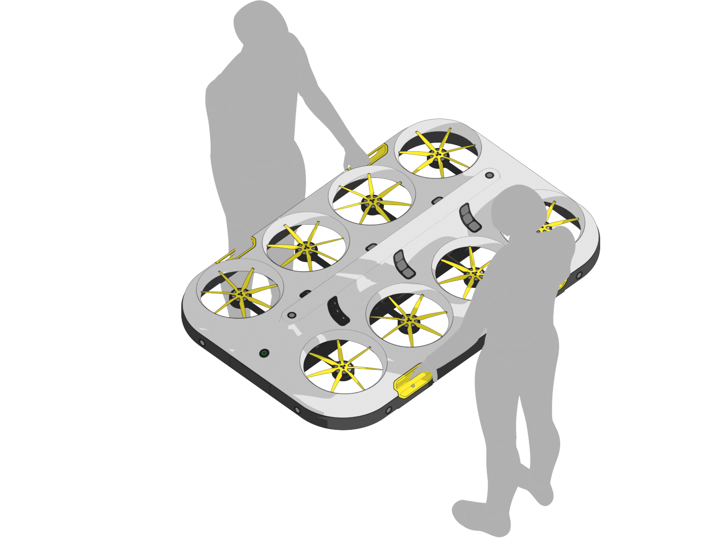
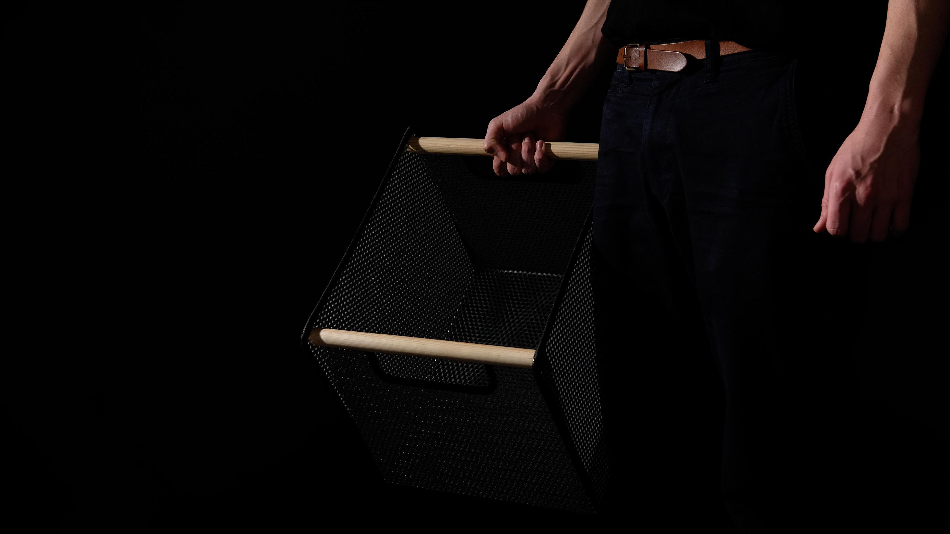
Carrying the drone.
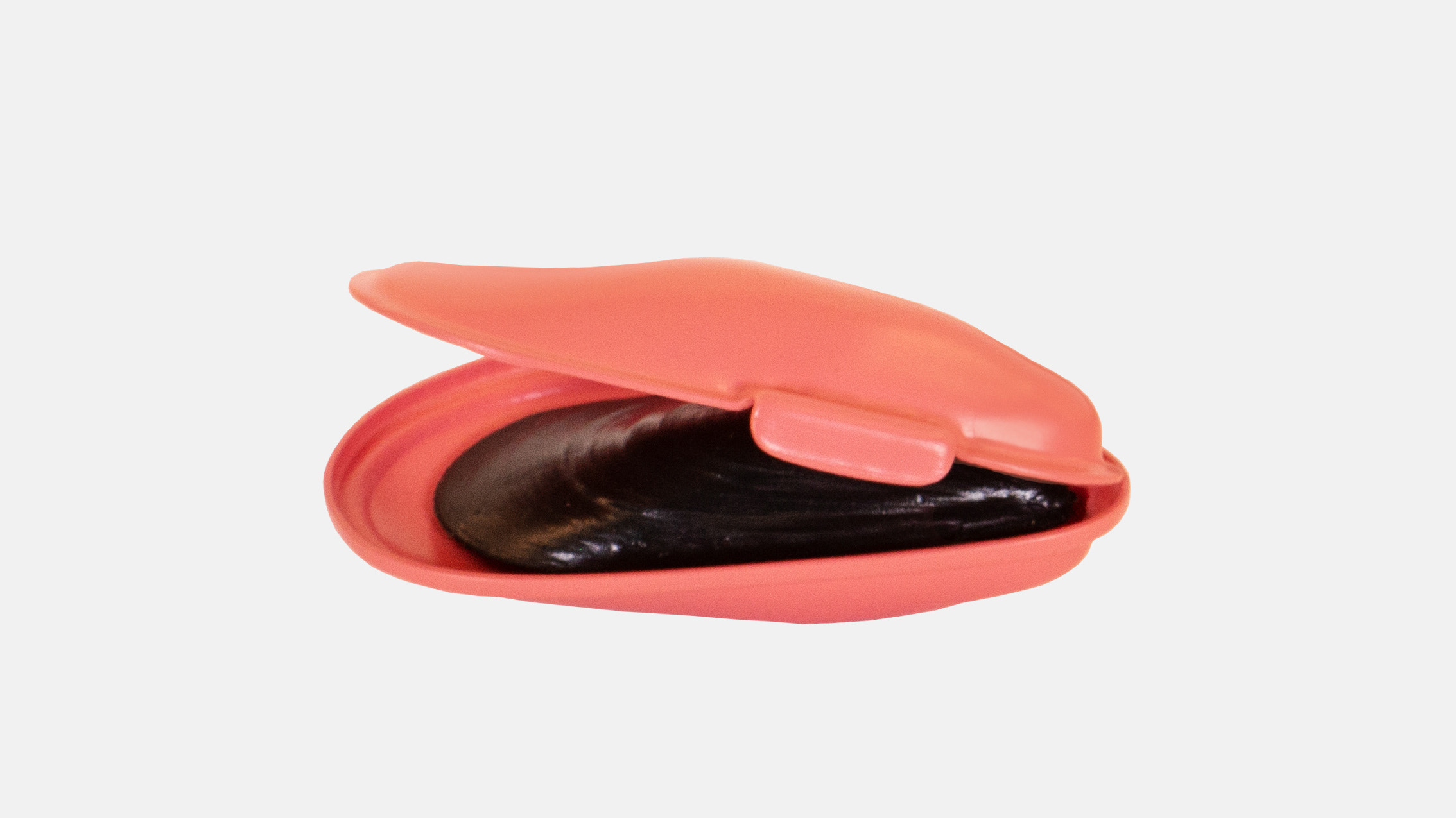
Inserting and replacing the battery.

Mapping and forographing the sewer.
Mapping and forographing the manhole.

DESIGN